English
A properly designed borewell slotted pipe can significantly improve groundwater well performance by creating a controlled pathway for groundwater to enter the well while limiting the movement of formation particles. The right screen design helps balance water inflow, sand control, hydraulic efficiency, structural strength, and long-term operating stability.
However, the performance of a slotted pipe does not depend on slotting alone. Slot width, open area, slot pattern, screen length, pipe diameter, wall thickness, aquifer characteristics, gravel-pack design, installation quality, and well development all influence the final result. For drilling contractors, groundwater engineers, irrigation projects, and well-development companies, these factors should be evaluated as one integrated well-completion system.
The primary function of a borewell slotted pipe is to provide a controlled intake zone between the surrounding aquifer and the well interior. Groundwater can pass through the openings into the well, while the screen helps restrict the entry of formation material and properly sized filter-pack particles.
This controlled intake has several important effects:
Provides a defined area for groundwater entry
Distributes inflow across the productive aquifer interval
Helps control sand and fine-particle migration
Supports stability around the screened section
Can reduce excessive entrance velocity when sufficient open area is provided
Helps maintain predictable pumping performance
A groundwater well should therefore not be viewed simply as a drilled hole containing a pump. The aquifer, borehole, gravel pack, screen, casing, pump, and development process form a hydraulic system. A restriction in the screen or filter zone can increase head loss, raise drawdown, and reduce the effective capacity of the well.
This is why a slotted pipe for borewell should be specified according to actual formation and operating conditions rather than selected only by outside diameter.
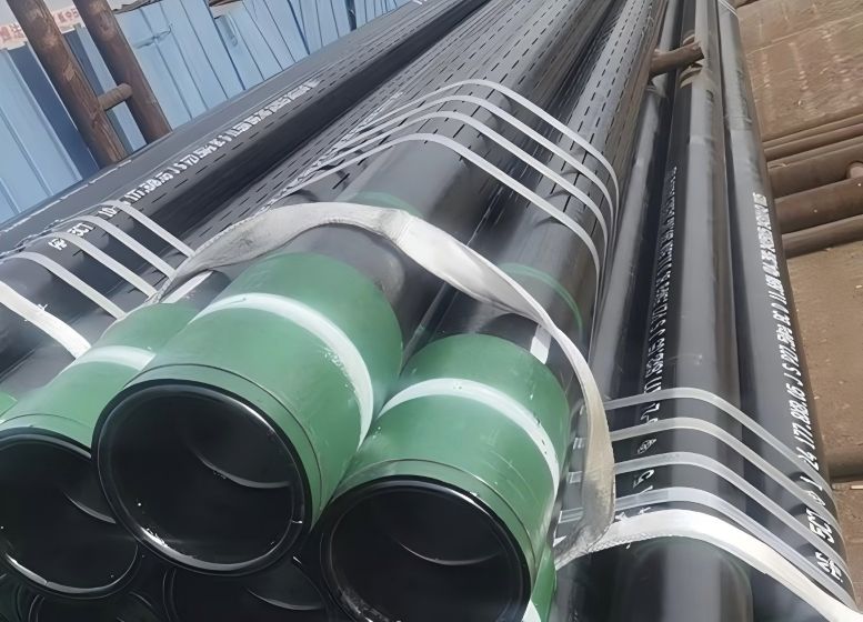
Slot size is one of the most important specifications when designing a slotted borewell screen. It determines how easily water can enter the well and how effectively the screen can retain surrounding particles.
If the slot opening is too large, formation sand or gravel-pack material may enter the well. Excessive sediment production can cause:
Sand accumulation inside the well
Increased wear on pumps and valves
Reduced effective screen area
Higher maintenance requirements
Formation instability around the screen
Potential deterioration of water quality
If the slot opening is too small, the screen may provide good particle retention but create unnecessary hydraulic resistance. Fine particles can also accumulate around the screen surface and gradually reduce effective permeability.
The correct objective is therefore not the smallest possible slot or the largest possible opening. The objective is to select an opening that provides an appropriate balance between groundwater inflow and particle retention.
Professional slot selection should normally consider:
Formation grain-size distribution
Effective grain size
Formation uniformity
Natural formation characteristics
Gravel-pack grading, where applicable
Required pumping rate
Expected entrance velocity
Screen open area
Well development method
Expected sediment-production tolerance
For unconsolidated aquifers, sieve analysis can provide valuable information about the particle-size distribution of the water-bearing formation. For gravel-packed wells, screen openings should be evaluated together with the selected filter-pack material.
A screen opening that looks appropriate from a dimensional perspective can still be unsuitable if the formation contains a large proportion of mobile fines. Conversely, an excessively restrictive screen can limit the hydraulic efficiency of an otherwise productive aquifer.
Screen open area refers to the portion of the pipe surface available for groundwater to enter the well. Adequate open area is important because it reduces the hydraulic restriction imposed by the screen.
However, maximizing open area is not automatically the best engineering solution.
Increasing the number or size of slots removes more material from the pipe wall. Depending on pipe dimensions and slot arrangement, this can influence mechanical strength and resistance to external loading. The screen must therefore provide sufficient hydraulic intake without compromising the structural requirements of the well.
For a high-capacity borewell, engineers should consider the relationship between:
Total slot area
Screen diameter
Screen length
Groundwater flow rate
Entrance velocity
Formation permeability
Gravel-pack permeability
A screen with a large nominal open area can still perform poorly if the productive aquifer is incorrectly screened, the gravel pack is poorly installed, or the screen becomes clogged during operation.
Groundwater does not simply pass through the screen at one uniform velocity. Flow concentrates at the individual openings, and the resulting entrance velocity can influence hydraulic losses and particle movement.
When the effective open area is insufficient for the required pumping rate, water must enter through a relatively restricted surface area. This can increase local flow velocity and contribute to higher entrance losses.
A properly designed screen therefore aims to provide enough effective intake area so that groundwater can enter without unnecessarily high velocity.
This is particularly important for high-yield wells where pump capacity is substantial and sustained production is expected.
The arrangement of slots around the pipe determines how the intake area is distributed across the screen surface. Common configurations include straight longitudinal slots, staggered slots, and multiple-slot or gang patterns.
A straight slot pattern is relatively simple to manufacture and inspect. Staggered patterns can distribute openings more evenly around the circumference, while higher-density slot arrangements can provide increased open area when the pipe's mechanical requirements permit them.
The selected configuration should be based on the required combination of:
Hydraulic intake capacity
Particle retention
Remaining pipe-wall strength
Formation characteristics
Installation requirements
Manufacturing tolerances
For this reason, a technical purchase specification should state more than simply "slotted casing." It should identify slot width, slot length, slot pattern, spacing, pipe outside diameter, wall thickness, steel grade, total length, and connection requirements.
A gravel pack acts as a controlled filter zone between the surrounding formation and the slotted pipe. In a properly designed gravel-packed well, groundwater passes through the aquifer, enters the filter material surrounding the screen, and then flows through the screen openings into the well.
The gravel pack can provide several important functions:
Formation stabilization: It helps stabilize unconsolidated material around the screened interval.
Particle retention: It provides an intermediate filtration layer before water reaches the screen.
Hydraulic transition: It creates a relatively permeable zone around the well screen.
Improved inflow conditions: Properly graded filter material can support more uniform groundwater movement toward the screen.
The screen and gravel pack must therefore be designed together.
One common specification mistake is to select the slotted pipe first and determine the filter-pack requirements later. A more reliable process begins with aquifer characteristics, establishes the required filter-pack grading, and then determines a compatible screen opening.
The completion method affects how the screen should be designed.
In a naturally developed well, the screen is selected to retain the appropriate formation particles while allowing groundwater to enter. The surrounding formation becomes the primary filter zone.
In a gravel-packed well, the manufactured filter material provides an additional filtration layer. This can be particularly useful in formations where the natural grain-size distribution is unsuitable for a stable screen-only completion.
The choice between these approaches should be made based on geological conditions, formation stability, required yield, well diameter, and project economics.
Screen length should correspond to the productive water-bearing interval rather than simply covering the entire borehole.
If a screen is unnecessarily extended into low-productivity or unsuitable formations, the additional length may provide little useful groundwater while increasing material and installation costs. It can also introduce water from zones with different chemical characteristics.
The productive interval can be evaluated using a combination of:
Drilling records
Lithological samples
Geophysical logging
Formation characteristics
Water-level measurements
Pumping-test data
Groundwater-quality information
In heterogeneous formations, selecting the screened interval carefully can be more important than simply increasing total screen length.
The goal is to place the intake area where the aquifer can provide sustainable groundwater flow.
A longer screen does not automatically produce a proportionally higher well yield. If portions of the aquifer have low permeability, contribute little water, or present undesirable water-quality characteristics, extending the screen through those zones may create additional problems without improving useful production.
Screen placement should therefore follow hydrogeological evidence rather than a simple preference for maximum screen length.
Pipe diameter must provide adequate clearance for the selected pump and rising main while allowing appropriate annular space for installation materials.
The designer should evaluate the relationship between:
Borehole diameter
Screen outside diameter
Pump outside diameter
Pump setting depth
Rising-main dimensions
Gravel-pack thickness
Centralizer requirements
Installation tolerances
Wall thickness is equally important because the screen must withstand installation loads and external pressure after it is placed underground.
Slotting modifies the original pipe wall. Consequently, the structural behavior of a slotted section cannot always be treated as identical to that of an unmodified pipe with the same nominal dimensions.
External loading can come from hydrostatic pressure, formation movement, installation forces, pipe handling, and other downhole conditions. Slot width, slot spacing, slot orientation, wall thickness, and pipe ovality can all influence the final mechanical performance.
For projects requiring blank casing together with screened sections, the entire casing string should be designed as a compatible assembly.
The casing should provide appropriate mechanical support while the screen provides the required hydraulic intake area.
The appropriate steel grade depends on well depth, mechanical loading, water chemistry, corrosion conditions, expected service life, installation method, and applicable project specifications.
J55 and N80 casing bodies can be used as the basis for slotted pipe in suitable applications. However, choosing a material grade should never be based on grade name alone.
A proper specification should evaluate:
| Parameter | Why It Matters |
|---|---|
| Steel grade | Determines specified mechanical properties and material suitability |
| Wall thickness | Influences structural and collapse performance |
| Slot width | Controls particle retention and hydraulic intake characteristics |
| Slot pattern | Determines how open area is distributed around the pipe |
| Open area | Influences potential groundwater intake and entrance losses |
| Pipe diameter | Determines pump clearance and annular space |
| Corrosion conditions | Influence long-term service life |
| Connection type | Determines compatibility with adjacent casing sections |
| Inspection requirements | Provide dimensional and material verification |
Material selection should ultimately follow the complete engineering specification rather than being driven only by initial purchase price.
The quality of the slot itself can directly affect screen performance. Poorly controlled machining may result in inconsistent slot width, irregular spacing, burrs, distorted edges, or localized weakening of the pipe wall.
For groundwater applications, these details matter because the slot opening is the actual interface through which water and particles interact with the screen.
Important manufacturing checks can include:
Slot width measurement
Slot length verification
Slot spacing inspection
Open-area verification
Visual inspection of slot edges
Pipe diameter and wall-thickness measurement
Steel-grade verification
Overall length inspection
End-connection inspection
JRSK focuses on controlled slot configurations and customized slotted-pipe production for applications requiring specific opening dimensions and patterns. This allows project specifications to be translated into a defined pipe configuration instead of relying on a generic market product.
Even a well-designed slotted pipe can underperform if the well is inadequately developed after installation.
Drilling operations can disturb the formation around the borehole and introduce fine material or drilling-fluid residues into the area surrounding the screen. These materials can reduce local permeability and increase hydraulic resistance.
Well development is intended to improve the hydraulic connection between the aquifer and the well by removing undesirable fine material from the screen and surrounding formation.
Depending on well design and site conditions, development may involve controlled pumping, surging, air lifting, or other methods selected by the well contractor.
The objective should be a stable well that can deliver the required production rate without excessive sediment and excessive drawdown.
Screen selection and well development should therefore be treated as complementary stages of the same completion process.
An opening that is too large can allow excessive sediment to enter the well, while an opening that is too small can increase hydraulic resistance and clogging risk.
When the effective intake area is too small for the required production rate, groundwater must enter through a relatively restricted area, potentially increasing entrance velocity and screen-related head loss.
Installing the screen across low-productivity or unsuitable formations can reduce the effectiveness of the completed well even when the screen itself is manufactured correctly.
Bridging, segregation, contamination, or inappropriate filter material can reduce the permeability of the filter zone around the screen.
Residual fines and drilling-fluid materials can remain around the screen and restrict groundwater movement.
A pump that extracts groundwater faster than the aquifer can sustainably supply may produce excessive drawdown and increase the hydraulic demand placed on the screen.
Depending on groundwater chemistry, mineral deposits or corrosion products can progressively reduce effective opening area and affect pipe integrity.
There is no universal answer because the preferred intake design depends on the aquifer, particle-size distribution, well-completion method, structural requirements, and target production rate.
| Factor | Slotted Pipe | Perforated Casing |
|---|---|---|
| Opening geometry | Controlled longitudinal or patterned slots | Individual holes or perforations |
| Particle control | Can provide controlled opening width | Depends strongly on hole diameter and arrangement |
| Flow distribution | Can be distributed along defined slot bands | Depends on perforation pattern |
| Open-area design | Controlled through slot width, length, number, and pattern | Controlled through hole size, quantity, and spacing |
| Customization | Slot dimensions and patterns can be customized | Hole dimensions and patterns can be customized |
| Sand-control potential | Strong when matched to formation or filter pack | Depends heavily on formation and opening design |
| Structural considerations | Must account for material removed through slots | Must account for material removed through perforations |
| Typical selection basis | Formation and filter-pack requirements | Formation, flow requirements, and structural design |
Rather than asking which product is universally better, engineers should compare the complete screen design against the formation and operating requirements.
The quality of the initial technical specification has a major influence on the final well-completion result.
Before requesting a quotation, the buyer should ideally provide:
Borehole diameter
Required screen outside diameter
Total well depth
Proposed screened interval
Aquifer formation description
Formation grain-size information
Natural-pack or gravel-pack completion method
Gravel-pack specification, where applicable
Required slot width
Required open area or slot quantity
Slot pattern
Pipe wall thickness
Steel grade
Required pipe length
Connection requirements
Expected pumping rate
Pump outside diameter
Groundwater corrosion conditions
Installation method
Inspection and documentation requirements
Providing this information enables the manufacturer to evaluate the application rather than simply quoting a standard product according to diameter and length.
| Selection Factor | Recommended Approach | Potential Risk |
|---|---|---|
| Slot width | Determine from formation or filter-pack analysis | Selecting a standard slot without geological data |
| Open area | Balance hydraulic demand with pipe strength | Maximizing open area without structural review |
| Screen length | Match productive aquifer intervals | Screening unsuitable zones |
| Pipe wall | Check against external loading and slot geometry | Selecting wall thickness only by price |
| Steel grade | Match mechanical and environmental requirements | Choosing grade without considering service conditions |
| Gravel pack | Design together with slot opening | Choosing filter material independently |
| Installation | Plan centralization and placement carefully | Treating installation as routine handling |
| Well development | Include development in the completion plan | Ignoring development until production problems occur |
| Inspection | Verify dimensions, materials, and slot geometry | Relying only on visual inspection |
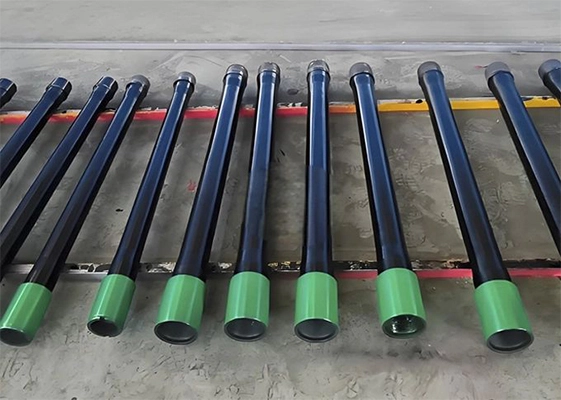
JRSK is a manufacturer and supplier of steel tubular products serving international customers in demanding casing, tubing, and well-related applications. Its product range includes slotted pipes, casing pipes, tubing, couplings, pup joints, and other steel tubular products.
For borewell applications, JRSK can manufacture slotted pipe configurations according to specified slot dimensions, patterns, pipe dimensions, and material requirements. This is particularly important for projects where the screen must be matched to an aquifer, gravel-pack design, target flow rate, or installation configuration.
Instead of treating slotted pipe as a generic commodity, JRSK's approach allows the buyer to define the technical characteristics required for the application. This can include pipe-body specifications, slot arrangement, opening dimensions, screen length, and other project-specific requirements.
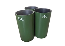
For projects requiring a complete casing string, screened sections can also be coordinated with compatible blank casing and other tubular components. This can simplify procurement and reduce the risk of dimensional incompatibility between different sections of the well completion.
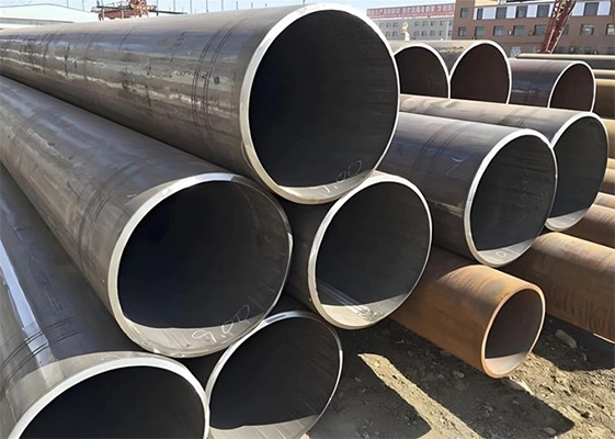
Where a project requires supporting tubular products, JRSK's range also includes casing pipe and seamless pipe, allowing buyers to coordinate different components through one tubular-product supplier.
The main purpose is to provide a controlled groundwater intake area while limiting the movement of formation particles or filter-pack material into the well. Its effectiveness depends on slot size, open area, screen placement, gravel-pack design, and well development.
There is no universal slot size. The appropriate opening should be selected according to formation grain-size characteristics or the grading of the filter pack used around the screen. The required production rate and expected entrance velocity should also be considered.
Not necessarily. Larger openings may provide greater potential intake area, but they can also allow unwanted particles to enter the well. The best screen balances hydraulic capacity with particle retention and long-term clogging resistance.
A properly designed gravel pack creates a permeable transition zone around the screen. It can stabilize unconsolidated formation material, improve particle retention, and provide favorable conditions for groundwater to move toward the screen.
J55 and N80 casing bodies can be used as the basis for slotted pipe in suitable applications. The final material choice should consider well depth, external loading, groundwater chemistry, corrosion conditions, pipe dimensions, and the project's technical specification.
It can improve performance when the existing completion has an unsuitable intake design, excessive hydraulic restriction, damage, or poor particle control. However, low well yield can also result from aquifer decline, clogging, scaling, pump problems, or inadequate development. The cause should be identified before replacing or modifying the screen.
Borewell slotted pipes improve groundwater well performance when they are correctly engineered as part of the complete well-completion system. Their contribution extends beyond allowing water to enter the well. A well-designed screen can provide controlled groundwater intake, support particle retention, distribute inflow across productive aquifer zones, and contribute to stable long-term operation.
The most important factors are slot width, open area, slot pattern, screen length, pipe diameter, wall thickness, steel grade, gravel-pack compatibility, installation quality, and well development. These factors should be evaluated together rather than selecting a slotted pipe based on one dimension or the lowest purchase price.
For drilling contractors, groundwater engineers, irrigation developers, and procurement teams, the most reliable approach is to start with aquifer and well data, establish the required hydraulic and structural conditions, and then specify the slotted pipe accordingly. A manufacturer should have enough technical information to recommend or manufacture a configuration that matches the actual application.
JRSK provides customized slotted steel pipe solutions for borewell and well-completion applications, helping customers balance groundwater inflow, particle control, structural performance, and project-specific manufacturing requirements. Properly selected and installed, a borewell slotted pipe can become an important component in achieving reliable groundwater production and maintaining well performance over the service life of the installation.
https://www.epa.gov/foia/design-and-installation-monitoring-wells-guidance
https://www.api.org/products-and-services/standards/important-standards-announcements/spec5ct