English
A borewell screen is not simply a pipe with openings. It is a hydraulic intake, a formation-control component and a structural member installed in an environment that may be abrasive, corrosive and difficult to access after completion. A selection that looks economical at the quotation stage can create high entrance velocity, sand production, pump wear, unstable yield or early collapse if the slots, pipe body and installation method are not matched to the formation.
This guide is written for drilling contractors, water-well developers, mine dewatering teams, civil engineers and procurement specialists who need to specify a steel slotted pipe with enough detail for technical comparison. It explains which site data matter, how slot width and open area influence performance, where J55 or N80 bodies may be appropriate, and what information a buyer should submit before asking JRSK for a recommendation.
The dimensions and values in this article are practical engineering references rather than a substitute for a project design. Final slot geometry, strength, material and corrosion protection should be verified against the bore log, particle-size distribution, water chemistry, installation depth, operating drawdown and the applicable local standard.
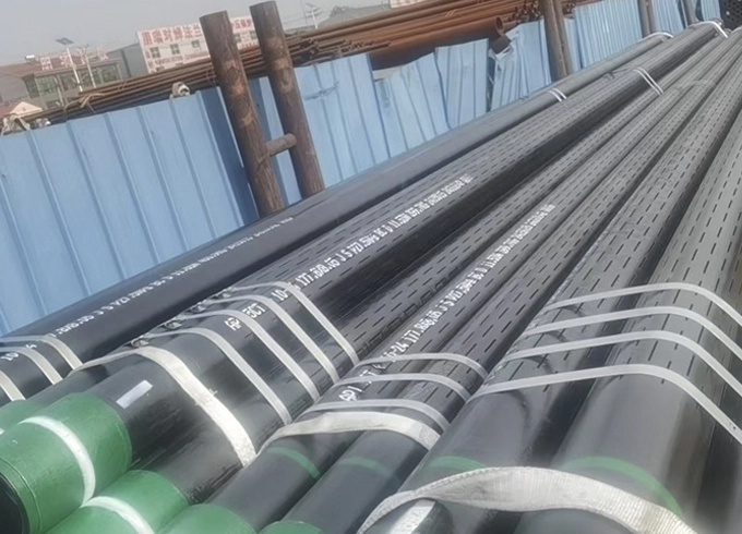
A slotted pipe for borewell use is a casing or screen section with controlled longitudinal, staggered or patterned openings that admit groundwater while limiting the entry of formation particles and supporting the completed bore.
In many borewell projects, the slotted section is placed opposite the water-bearing formation. Blank casing is used above, below or between screened intervals where fluid entry is not required. A gravel pack may be installed in the annular space to create a graded filter between the native formation and the screen. The screen therefore works as part of a system: formation, gravel pack, slot opening, pipe wall, pump setting and operating rate all interact.
The product may be described as slotted casing, slotted well pipe, screen casing, slotted liner or borewell slotted pipe. These names are sometimes used interchangeably, but a purchase specification should not rely on the product name alone. It should state the outside diameter, wall thickness, body grade, length, slot width, slot length, slot pattern, number of slots, required open area, end connection, surface treatment and inspection documents.
JRSK manufactures steel pipe products for oilfield, water-well and industrial applications. Buyers reviewing a slotted pipe for borewell should use the product page as the commercial landing page and use technical articles like this one to confirm the selection logic before requesting a quotation.
Slot size is the clear opening across each cut, and it controls the particle size that can pass through the screen as well as the hydraulic resistance at the intake surface.
A slot that is too wide can allow formation sand or gravel-pack particles to enter the well. The immediate symptoms may be cloudy discharge, sediment accumulation and rapid pump abrasion. In severe cases, continuous particle movement can destabilize the surrounding formation and create voids around the screen. A slot that is too narrow can retain particles effectively but reduce open area, increase entrance velocity and make the screen more vulnerable to clogging by fines, scale or biological growth.
The correct slot opening is normally selected from a sieve analysis rather than from bore diameter alone. A representative sample should be taken from each water-bearing interval. The material is dried, separated through a stack of sieves and plotted as a grain-size distribution. The design method then relates the screen opening to a selected retained percentage and to whether the well will be naturally developed or gravel packed.
There is no universal rule that every formation should use a 0.5 mm, 0.75 mm or 1.0 mm slot. Those values may be common in certain markets, but the same opening can perform very differently in a uniform coarse sand, a widely graded sand, a silty formation or an engineered gravel pack. The buyer should request a slot recommendation based on actual particle data whenever the well is important, deep or difficult to rehabilitate.
For comparison, a “20-slot” water-well screen commonly refers to an opening of 0.020 inch, which is approximately 0.508 mm. USGS borehole completion records show real projects using 0.020-inch openings, but those records demonstrate a project choice, not a universal standard. The value must still be matched to the formation and filter design.
Sieve-based screen selection is a process of matching the screen opening and filter pack to the grain-size curve so that water can enter efficiently while the surrounding material remains stable.
Begin by dividing the bore log into hydraulically meaningful intervals. Samples taken from different depths should not be blended if the formations are materially different. A coarse sand lens and a fine silty sand may require different slot sizes or separate screened intervals. The final design should also consider whether the pump intake will be near the screen and whether the well is expected to operate continuously or intermittently.
For a naturally developed well without an artificial gravel pack, the screen must retain a suitable portion of the native formation. The design target depends on uniformity, grain shape and the development method. In a gravel-packed well, the engineer first selects a pack grading that is compatible with the formation and then chooses a slot opening that retains most of that pack. The screen opening is therefore selected against the pack, not directly against the finest native particles.
A practical procurement workflow is:
Provide the bore log and mark the proposed screened intervals.
Provide sieve-analysis results for each interval, preferably as a cumulative percentage passing curve.
State whether a gravel pack will be installed and provide its proposed grading.
State the target pumping rate, static water level and anticipated drawdown.
State the bore diameter, screen outside diameter and available annular space.
Ask the manufacturer to show the proposed slot width, pattern, number of slots and calculated open area.
Confirm that the proposed slot tolerance is compatible with the selected filter material.
Procurement teams often ask only for “slotted pipe 6 inch” or “borewell screen 8 inch.” That request is incomplete because two pipes with the same outside diameter can have very different intake capacity and sand-control performance. A technically comparable quotation requires the same slot geometry and open-area requirement across suppliers.
Open area is the total area of all inlet openings divided by the external surface area of the screened section, usually expressed as a percentage.
Open area affects the velocity of water entering the screen. For a given pumping rate, more effective inlet area generally reduces entrance velocity. Lower entrance velocity can reduce head loss and may reduce the movement of fines at the screen interface. However, theoretical open area is not the same as effective open area. Part of the pipe surface may be blocked by formation, gravel bridging, incrustation or poor slot distribution.
A simplified open-area calculation for rectangular slots is:
Total slot area = number of slots × slot width × slot length.
Open area percentage = total slot area ÷ external surface area of the screened length × 100.
For example, assume a 1.5 m screen section has 300 slots. If each slot is 0.75 mm wide and 50 mm long, the theoretical slot area is 300 × 0.75 × 50 = 11,250 mm². This equals 0.01125 m². If the pipe outside diameter is 73.0 mm, the external cylindrical area over 1.5 m is approximately π × 0.073 × 1.5 = 0.344 m². The theoretical open area is therefore about 3.27 percent.
This calculation is useful for quotation comparison, but it does not prove that the screen will deliver the target flow. The engineer must also consider slot entrance shape, internal burrs, gravel-pack permeability, formation permeability, well development and the amount of screen exposed to productive formation.
| Design Variable | If Increased | Potential Benefit | Potential Risk |
|---|---|---|---|
| Slot width | Wider opening | More inlet area and lower clogging risk in coarse formations | More sand or pack particles may enter |
| Slot length | Longer cuts | More open area without increasing slot count | May reduce local pipe-wall strength if excessive |
| Number of slots | More openings | More distributed inflow | More machining, inspection and possible strength reduction |
| Screened length | Longer intake interval | Lower inflow per unit length if formation is productive | May connect unwanted zones or increase project cost |
Slot pattern is the arrangement of openings around and along the pipe, and it influences inflow distribution, manufacturing time and the amount of remaining metal between adjacent cuts.
Straight or line patterns arrange slots in aligned bands. They are simple to inspect and can suit applications where a predictable orientation is required. Staggered patterns offset adjacent slots so that openings are distributed more evenly around the circumference. Gang or multiple-staggered patterns place more than one slot at each axial position and can increase open area, but the remaining ligaments must be checked carefully.
Perforated pipe uses drilled or punched holes rather than narrow slots. It can be suitable where the formation or gravel pack is coarse enough for larger openings, or where a specific inflow pattern is required. Wire-wrapped screens can deliver high open area and a continuous slot geometry, but they are a different product architecture with different cost, collapse and handling characteristics.
| Screen Type | Typical Opening Geometry | Main Advantage | Main Limitation | Best-Fit Use |
|---|---|---|---|---|
| Straight slotted steel pipe | Aligned longitudinal slots | Simple specification and inspection | Flow may be less evenly distributed if slot bands are sparse | General borewell and industrial intake applications |
| Staggered slotted casing | Offset longitudinal slots | More even circumferential distribution | Requires controlled machining and ligament spacing | Projects needing balanced intake around the pipe |
| Gang slotted pipe | Multiple offset slots per station | Higher potential open area | Greater effect on remaining wall strength | High-inflow designs after strength verification |
| Perforated casing | Round holes | Robust openings and easy visual inspection | Usually retains only coarser filter material | Coarse formations, drainage and selected oilfield applications |
| Wire-wrapped screen | Continuous V-shaped slot | High open area and controlled slot | Different price, structure and handling requirements | High-performance water wells and engineered completions |
Pipe dimensions must provide sufficient hydraulic clearance and structural capacity while fitting the drilled bore and leaving enough annular space for installation and gravel placement.
The inside diameter should allow the pump, cable, rising main and any monitoring equipment to be installed and removed. The outside diameter must leave sufficient annular space for gravel packing, centralizers and sealing materials. A larger diameter can reduce internal velocity and improve access, but it increases drilling, casing, gravel and handling cost.
Wall thickness cannot be selected only from nominal depth. Collapse risk depends on external pressure, formation movement, installation loads, water-level changes, ovality, slot pattern and the loss of metal caused by machining. A slotted section is not identical in strength to an uncut casing of the same nominal wall. The supplier should understand the slot layout before confirming structural suitability.
Screen length should correspond to productive intervals rather than simply occupying the entire open bore. A longer screen can reduce entrance velocity if it is opposite permeable formation, but screening low-permeability or poor-quality zones may add little yield and can create water-quality or sand-control problems. The bore log, geophysical data and pumping-test objectives should guide the interval design.
When the project also requires blank casing, buyers can compare products from established casing pipe suppliers and specify compatible outside diameter, wall, grade and end connections so that the blank and slotted sections form one continuous string.
The steel body grade identifies a mechanical-property class, but the correct borewell material also depends on corrosion, water chemistry, depth, handling and the required service life.
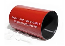
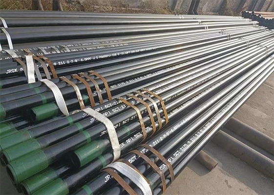
J55 and N80 petroleum casing bodies are often used as robust bases for machined slotted pipe. The grade designation should not be treated as a complete corrosion specification. Carbon steel can corrode in oxygenated, acidic, saline or microbiologically active water. A higher strength grade does not automatically provide better corrosion resistance.
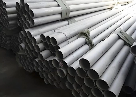
For ordinary groundwater with controlled chemistry and a service plan that allows rehabilitation, coated carbon steel may be economical. More aggressive environments may require a compatible coating, sacrificial allowance, stainless steel or another corrosion-resistant material. The coating system must tolerate machining edges, transportation, installation and water-service requirements. Any damaged coating at the slots or threads should be addressed in the inspection plan.
Material selection should review:
Chloride, sulfate, dissolved oxygen, pH and total dissolved solids.
Expected presence of iron bacteria or sulfate-reducing bacteria.
Static and dynamic water levels and whether the screen will be alternately wet and dry.
External soil or formation chemistry above the water-bearing zone.
Planned disinfection, rehabilitation chemicals and cleaning methods.
Required design life and the cost of future replacement.
JRSK can review body grade, dimensions and machining requirements, but the buyer or project engineer should retain responsibility for material compatibility with the site water chemistry.
Slotted-pipe quality depends on dimensional consistency, smooth openings, traceable pipe material and protection against damage during storage and transport.
Slot width should be measured at defined locations with an agreed method. A few hand measurements are not enough for a long order if slot tolerance is critical. The inspection plan can define sampling frequency, acceptable deviation and how burrs or heat-affected edges will be evaluated. Laser cutting, saw cutting or milling can each produce acceptable products when the process is controlled, but the resulting edge condition and tolerance may differ.
The buyer should also confirm straightness, outside diameter, wall thickness, length, thread condition, coupling compatibility, coating continuity and marking. Material traceability should connect each finished screen section to the pipe body heat or lot and to the relevant material certificate.
A practical pre-shipment document package may include:
Mill test certificate or material test report for the pipe body.
Dimensional inspection report.
Slot width, slot length, slot count and pattern record.
Calculated open-area sheet.
Visual inspection and burr-control record.
Thread gauge or end-connection inspection where applicable.
Coating report, if a protective system is specified.
Packing list with pipe identification and lengths.
Installation quality determines whether the selected screen performs as designed, because impact damage, poor centralization or incorrect gravel placement can negate a good factory specification.
The screen string should be handled with lifting equipment and supports that prevent bending, crushing or thread damage. Protectors should remain in place until connection. The pipe should not be dragged across abrasive ground or struck to force alignment. If threaded joints are used, the correct compound, clean threads and controlled make-up procedure are essential.
Centralizers help maintain annular space around the screen. Without adequate centralization, the gravel pack may be thin or absent on one side, creating uneven inflow and a direct path for formation material. Gravel should be clean, correctly graded and placed using a method that limits bridging. The installed volume should be compared with the calculated annular volume to identify losses or incomplete placement.
Well development removes drilling fluid, fines and unstable particles around the screen. Development should continue until discharge and sand content meet project criteria rather than stopping after a fixed time. Surging, airlifting, pumping or jetting methods should be selected for the formation and screen. Excessively aggressive development can damage the formation or screen; insufficient development can leave high head loss and persistent fines.
The pump intake should normally be positioned to avoid concentrated flow at a short section of screen. Pumping rate should be increased gradually during testing. Drawdown, recovery, discharge, turbidity and sand content provide evidence of whether the intake system is stable.
Most procurement failures begin with an incomplete request that allows suppliers to quote products with different hydraulic and structural characteristics under the same general name.
| Mistake | Likely Consequence | Corrective Action |
|---|---|---|
| Ordering only by outside diameter | Unknown slot size, open area, wall and grade | Issue a full data sheet with measurable requirements |
| Choosing slot size without sieve data | Sand pumping or excessive clogging | Use formation and gravel-pack particle curves |
| Comparing price per meter without open area | Low-cost screen may have much less intake capacity | Compare slot count, length and calculated open area |
| Ignoring wall-strength reduction | Deformation or collapse during installation or service | Review slot pattern and structural requirement together |
| Assuming higher steel grade means corrosion resistance | Unexpected corrosion in aggressive water | Evaluate chemistry and protective material system |
| No inspection acceptance criteria | Disputes over slot tolerance and burrs | Agree sampling, measurement and documentation before production |
A complete request for quotation gives JRSK enough project data to recommend a manufacturable screen while allowing the buyer to compare technical offers on an equal basis.
Include the application, country, well depth, bore diameter, target screen intervals, outside diameter, wall thickness, body material or grade, required lengths, end connection, slot width, slot length, slot pattern, number of slots or minimum open area, quantity, coating, inspection level, document requirements and delivery destination. Attach the bore log, sieve curve and water analysis when available.
For projects that include several OCTG or water-well components, the casing and tubing category can help buyers review related blank casing, tubing, couplings and accessories. However, the final RFQ should separate each item and its acceptance criteria instead of placing all requirements in one general description.
Ask the supplier to identify any assumptions in the quotation. If slot width is proposed rather than specified, request the design basis. If open area is stated, request the calculation. If a grade is offered as an alternative, request the mechanical properties and corrosion considerations. A technically transparent quotation reduces later changes and helps the drilling team plan installation equipment and materials.
Common openings may range from fractions of a millimeter to several millimeters, but there is no single standard slot size for every borewell. The correct opening should be selected from the formation or gravel-pack particle-size distribution. A 0.020-inch opening, approximately 0.508 mm, appears in some documented well completions, but it should be treated as a project example rather than a default.
Neither design is universally better. Narrow slots can retain finer filter material and distribute inflow through long openings. Round perforations can be robust and easy to inspect but usually require coarser surrounding material. The correct choice depends on particle size, required open area, wall strength, manufacturing tolerance and the intended application.
The required open area depends on pumping rate, screen length, formation permeability, gravel pack and allowable entrance velocity. Higher theoretical open area is generally beneficial only when it is structurally safe and effectively exposed to permeable formation. Buyers should request the supplier’s calculation and have the project engineer confirm that the selected screen length and open area suit the target flow.
J55 casing can provide a strong carbon-steel body for machined slots and is used in many demanding pipe applications. Suitability still depends on depth, external loads, slot pattern, remaining wall strength and water chemistry. J55 is a mechanical grade, not a corrosion-resistance guarantee, so coating or an alternative material may be necessary.
The report should identify the pipe, heat or lot, outside diameter, wall thickness, length, slot width, slot length, slot count, pattern, calculated open area and visual edge condition. It may also include material certificates, thread inspection, coating checks and photographs. Sampling frequency and acceptance tolerances should be agreed before production.
Use representative sieve data, select a compatible gravel pack, match slot size to the pack, centralize the screen, place gravel without bridging and develop the well until unstable fines are removed. Pump selection and gradual commissioning also matter. Persistent sand production should be investigated as a system issue rather than blamed only on the slot opening.
A reliable borewell screen specification connects geology, hydraulics, material strength, corrosion conditions, manufacturing tolerance and installation practice. The most important decision is not simply whether to buy a slotted steel pipe, but how the slot opening, open area, pattern and body are matched to the formation and the target pumping rate.
JRSK can review a complete bore log, sieve curve, dimensions and service requirements to prepare a technically comparable proposal. Before ordering, require a documented slot design, material traceability, dimensional inspection and a clear installation plan. That discipline reduces sand-control risk, protects the pump and gives the completed well a better chance of achieving stable yield.
ISO 11960:2020 — Steel pipes for use as casing or tubing for wells
American Petroleum Institute — API Specification 5CT, 11th Edition
USGS borehole completion report with documented well-screen dimensions and slot size